MicroFloats
Creating a autonomous ocean profiling robot to measure anthrpogenic carbon levels
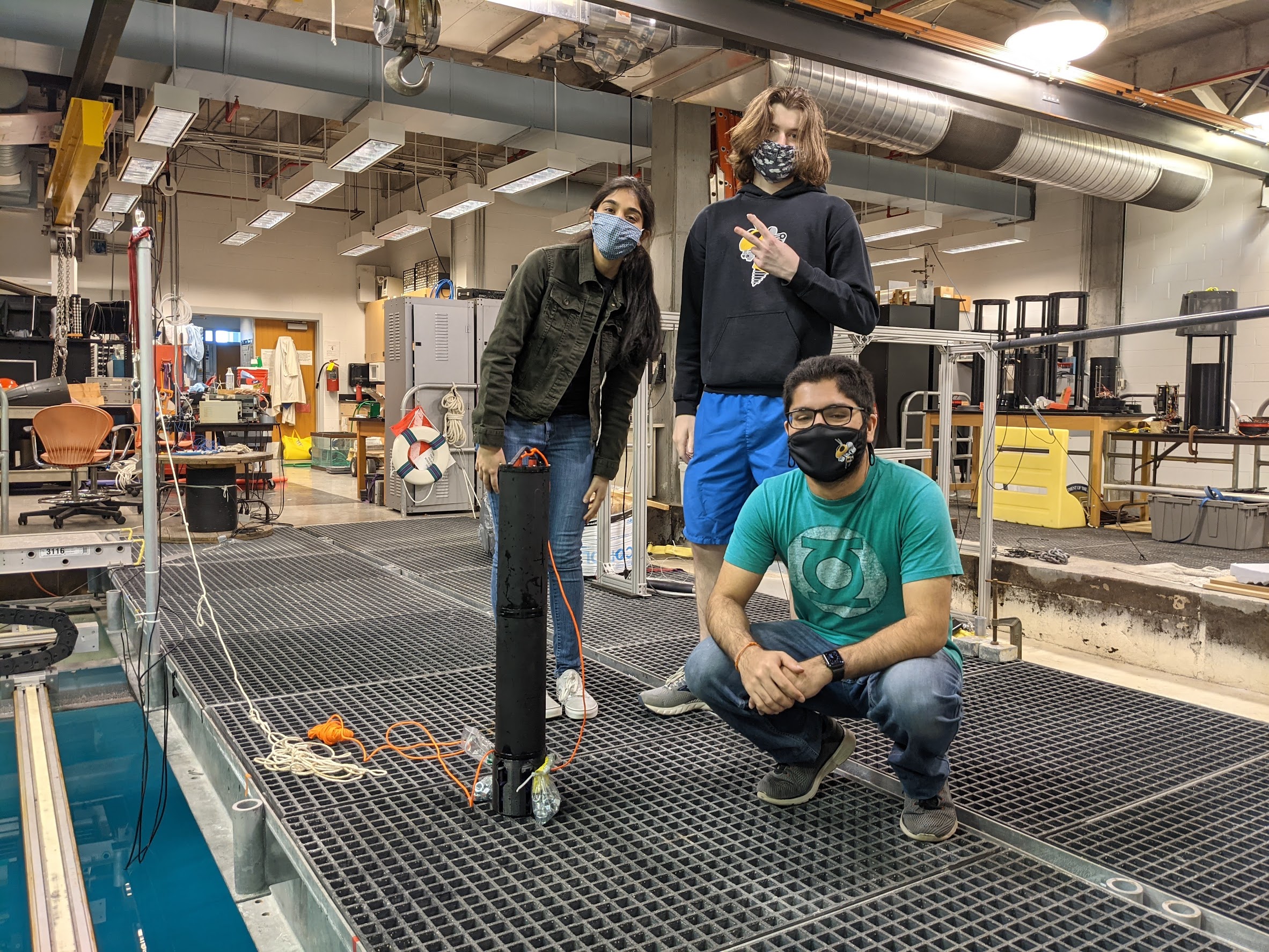
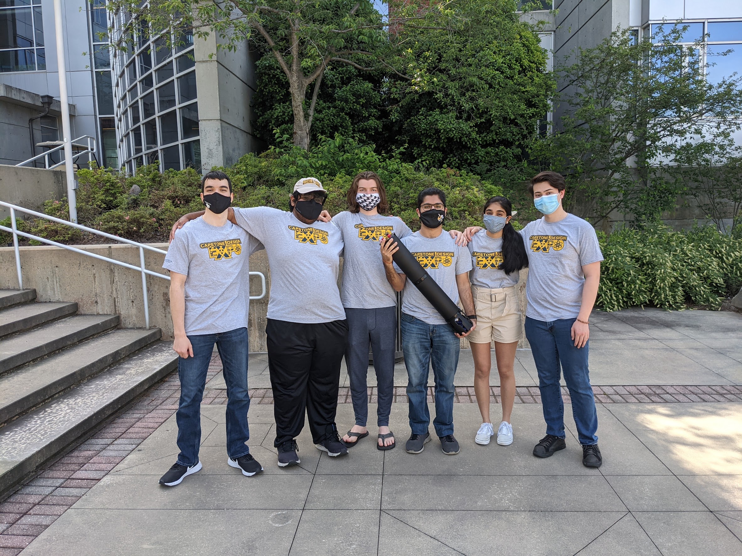
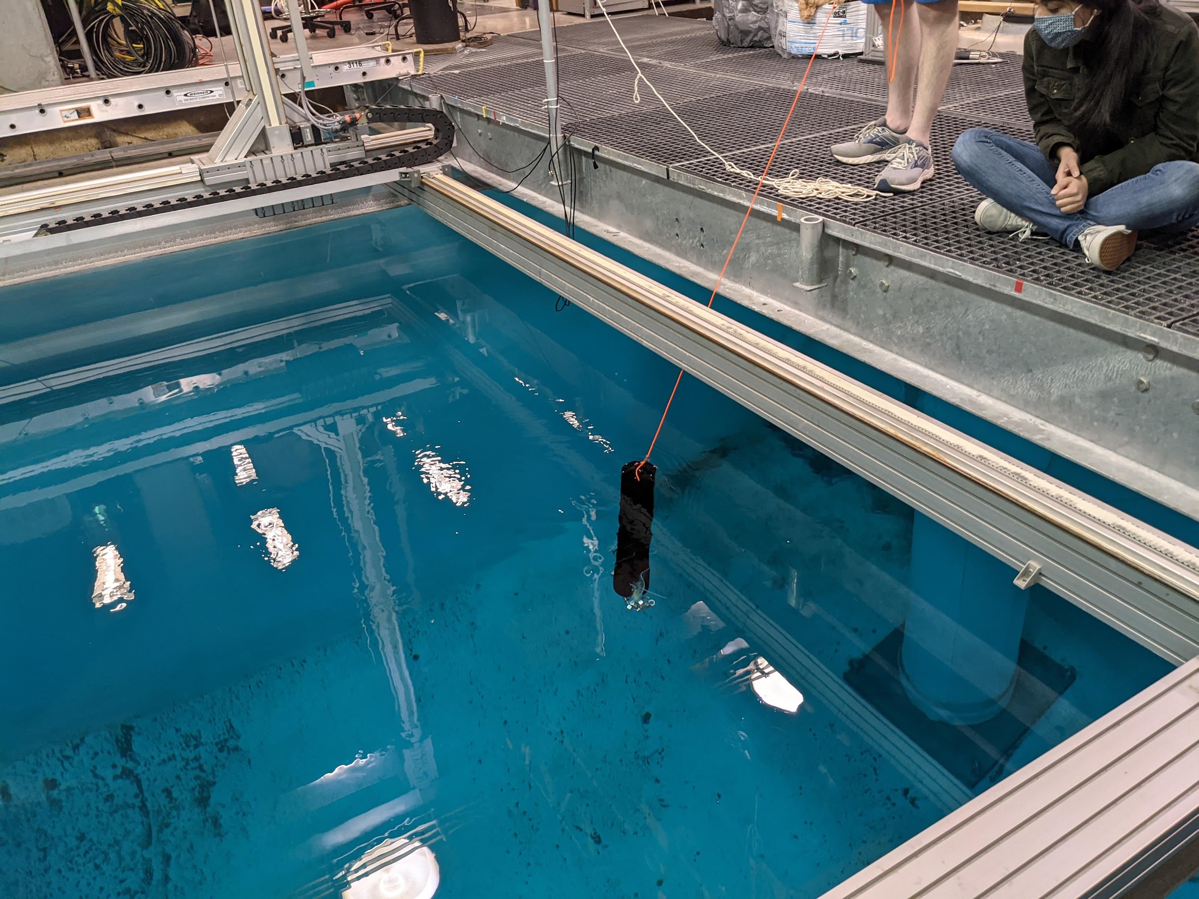
For my senior design project that I took my last semester of undergrad (Spring 2021), I, along with some of my friends from RoboJackets, designed, constructed, and tested an autonmous underwater robot. This robot - also known as a “MicroFloat” - was designed to profile different ocean depths while measuring various environmental factors affected by climate change, including carbon and pH levels. The end goal would be to produce multiple of these robots, forming a swarm that could profile a greater region of water.
On paper, our main requirements seemed relatively straightforward:
- Should be able to reach ocean depths of 1000 ft
- Should be able to communicate with other floats and a base station at all water depths
- Should be able to run continously for 1 week
- Should be able to gather various environmental data
- Complete the project within one semester with the assigned senior design budget of $1000
As with most engineering problems, we realized that during the design phase that these goals were unrealistic, especially within our timeframe and budget. Our final prototype shown here would be able to reach ocean depths of 400 ft.
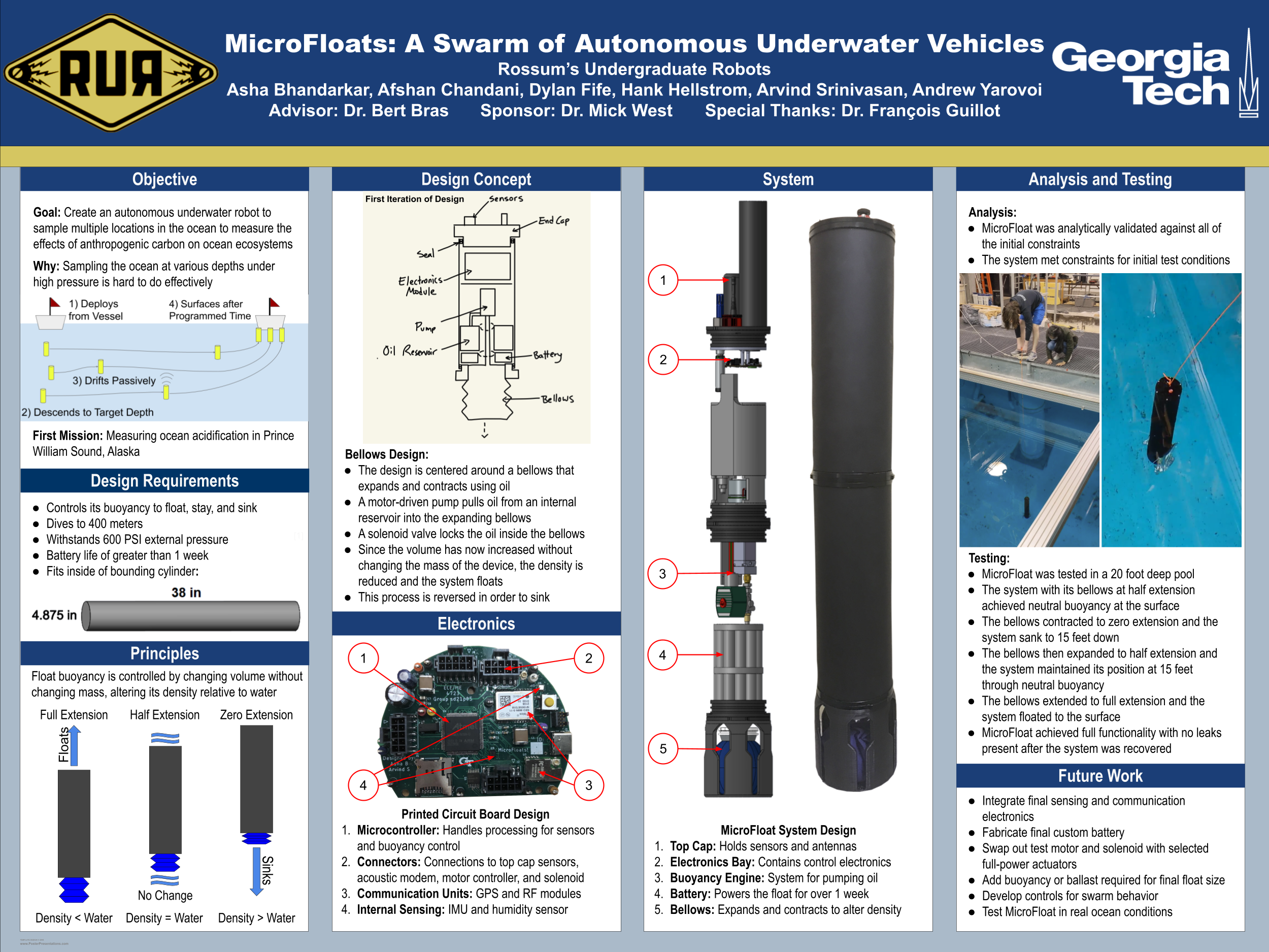
For the robot to ascend and descend to various ocean depths, we created a bouyancy engine that combined a pump, solenoid, and oil bladder to change the robot’s volume without changing mass, changing its density and therefore bouyancy. To make this a close looped system (i.e. be able to control oil levels which would adjust depth), we use a liquid level sensor to determine the amount of oil in the resevoir (versus the bladder) and a CTD sensor to measure depth in the water.
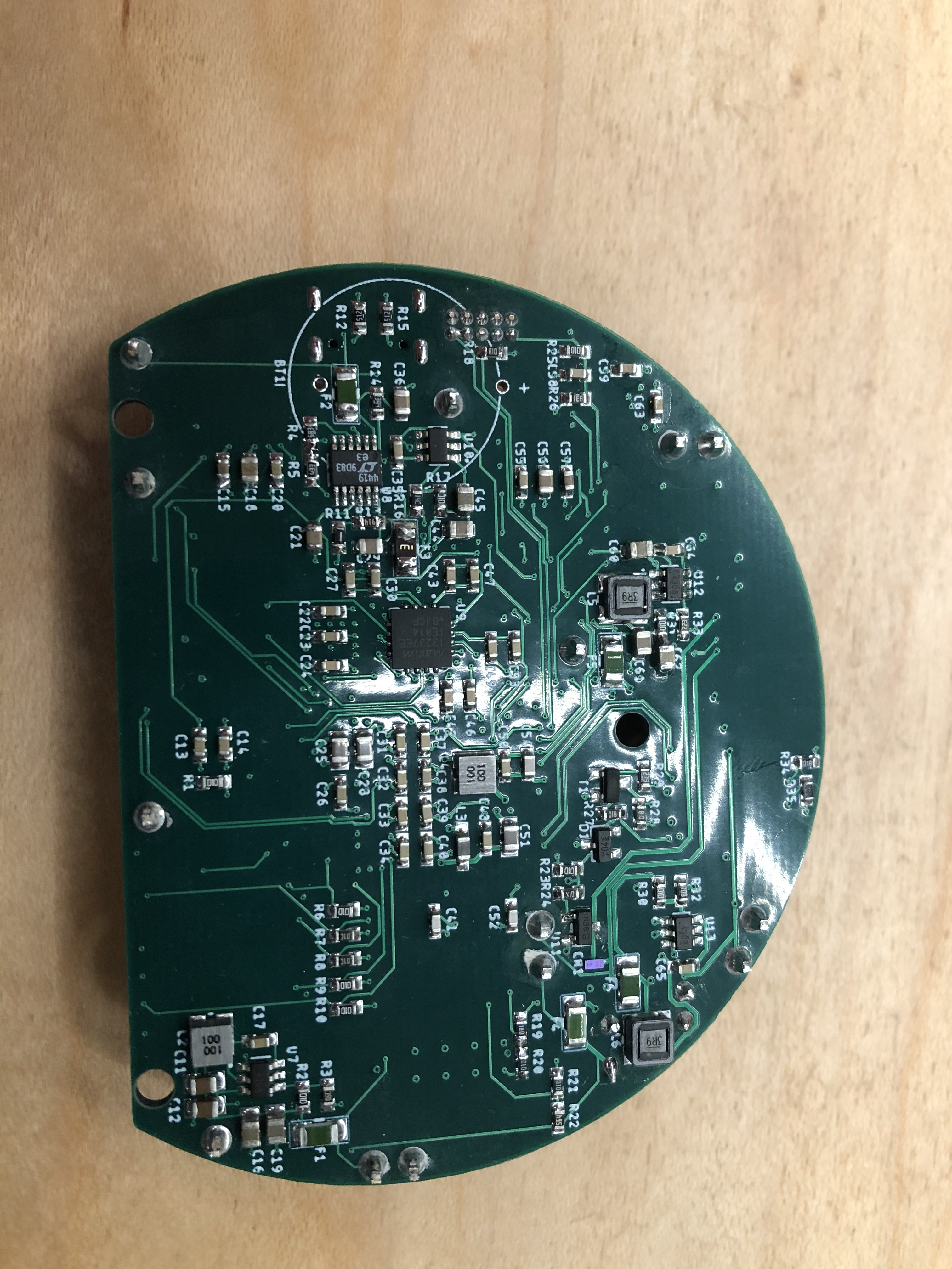
Electrically, there needed to be a way to interface with the various sensor, communication modules, the bouyancy engine controls, and distribute power. Therfore, my largest task for the project was creating a PCB that would be able to combine this functionality. The PCB incorporated various communication protocols to interface with the sensors and modules (UART, SPI, RS-232). For communcation underwater, the PCB interfaces with an off the shelf acoustic modem. For on the surface communication, RF 915 MHz with LoRa is used along with a GPS module for location information. To control the bouyancy engine, the PCB communicates through UART to an Odrive based brushless motor control as well as receiving analog sensor data from a liquid level sensor and a CTD sensor through UART. To distribute power, the PCB has various switching regulators to step down power.

This entire system was put together and tested in the Acoustic Water Tank in the Love Building, where we were able to see the float repeatledly ascend and descend to 15 ft without leaks or electrical failures (goals previous teams failed to achieve). Overall this was a very satifisying project to complete. It combined many things I’m passionate about - embedded systems, robotics, understanding climate change - but also many things I was unfamiliar with - underwater design parameters and creating incredibly low power systems.
If you’re interested in learning more about this project, including design reports, CAD, and code, visit the specific project website I have here!